研究開発室の馮 志聖(マイク)です。 Following the previous article: AR Remote Instructions base on ARKit
This time we will further discuss and explain in detail how to share 3D virtual objects.
Content
Introduction
The development of science and technology and the popularization of the Internet have brought many conveniences to people, especially the distance is no longer a barrier between each other. Due to the epidemic, the popularity of remote work has been accelerated. Video chat tools are often used in remote meetings, but the scope of applications is still limited, such as:
Case 1: In the factory. In the case of machine equipment failure, a maintenance person cannot arrive immediately because of remote work. When they try to remote maintenance use video chat on guide maintenance. They are impossible to grasp the damage of the equipment in detail, which will increase time and maintenance costs. If they use the AR remote instructions application to scan the target machine, it will have a 3d object with a good structure of the machine. Also sharing this 3d object with the maintenance person. The maintenance person can share the drawing of the mark on 3d object. It will improve this problem.
Case 2: In the field of interior design. The client wants to know whether the designer's work is suitable for his environment. In the absence of any environmental data file where the client is located, the designer only uses video chat, unable to observe the differences and details in detail. If they use the AR remote instructions application to scan the target area(like room or kitchen, etc...) or product(like chair or table, etc...), it will have a 3d object with a good structure and material of the target area or product. Also sharing this 3d object with the designer or client. The designer can add the product to 3d object of the target area, and design its style. The client can add the product to 3d object of the target area, and know whether the designer's work is suitable for his environment. It will improve this problem.
At present, only two cases are cited. Generally speaking, there may be more other cases. Based on various restrictions, we hope to develop software that can break through these restrictions.
In recent years, augmented reality technology*1 has grown rapidly. In the era of the popularization of mobile phones and the Internet, many technology companies firmly believe that augmented reality can bring people a more convenient life. There is a very important function in augmented reality technology, called depth estimation*2. The depth estimation generates a depth value from one or two images. The depth estimation function on mobile phones has always been a challenge and issue faced by various technology companies. Many technology companies want to improve this feature so that augmented reality technology can make it difficult to perceive 3d objects as virtual or real.
Among them, Apple is the first to launch mobile phones and tablets with LiDAR*3 sensors. LiDAR sensors are used to detect depth and distance. LiDAR is a method for determining ranges (variable distance) by targeting an object with a laser and measuring the time for the reflected light to return to the receiver. Before this, the equipment was very heavy and huge, inconvenient to carry, and required professionals to operate. After Apple launched this type of product, it has undoubtedly brought revolutionary changes to developers and consumers. For example, the depth detection of mobile phones was carried out through two or more cameras, their measured values of depth detection were not stable and accurate. Stereo photography techniques*4 are methods to produce stereoscopic images, videos, and films. However, after the launch of the LiDAR sensor, the stability and accuracy of depth detection have been greatly improved. Consumers can accurately test distances in daily life and scan objects in three-dimensional space through this sensor.
Three-dimensional(3D) scanning technology is a kind of scanning and copying real objects into digital data and accessing them. Before LiDAR sensors were introduced in the mobile phone field*5, the results of 3D scanning*6 were very rough and inaccurate. After the introduction of LiDAR sensors, this shortcoming was greatly improved.
Three-dimensional (3D) object(model)*7 represents a physical body using a collection of points in 3D space, connected by various geometric entities such as triangles, lines, curved surfaces, etc. Being a collection of data (points and other information), 3D models can be created manually, algorithmically (procedural modeling), or by scanning. Their surfaces may be further defined with texture mapping.
How to share 3D virtual objects outputted through 3D scanning in real-time and display them in augmented reality for multi-person remote collaboration will be the topic of the following chapters.
3D objects on AR Remote Instructions
Purpose
In the previous version of augmented reality remote collaboration*8, problems often appeared. That is, the remote and the local must have the same realistic target object at the same time. If one of them does not have one, then remote collaboration cannot be done. To improve this shortcoming, we have developed a system in which only one of the parties needs to have a realistic target object for remote collaboration. It uses 3D scanning technology to scan the real target object on remote collaboration. After the scan is completed, the digital information is shared with the other party in real-time. When both parties have virtual target objects, remote collaboration can be carried out. The specific process is shown in the figure below.
The upper part of the figure below is showing the preparation of a 3D model. The figure lists two ways. The first is through 3D scanning, and the second is through professional 3D design. After the preparation is completed, the digital information is output and shared in remote collaboration.

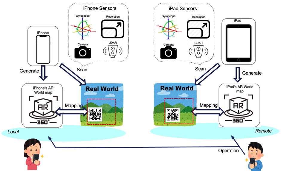
System Overview
The system architecture is shown in the following figure. The environment in the figure is divided into left and right sides. On the left are the equipment and multiple sensors used on the local side, and on the right are the equipment and multiple sensors used on the remote side. The two-party device renders the augmented reality based on multiple sensors, and the AR application recognizes the special icon (two-dimensional code*9 ) in the real environment, which is shown in the lower middle of the figure, setting it as the initial point and render the virtual scene*10 of the augmented reality. The subsequent various operations will match the feature points*11 nearby in the real environment based on the initial point.
Issue
We encountered a very important problem during the development process. First of all, our test environment is a mobile phone and a tablet computer. Because of the different setting parameters (like configure of the camera, configure of the inertial measurement unit (IMU)*12,...) of the two devices, the position of the three-dimensional object is wrong, and detailed remote collaboration is not possible.
As shown in the figure below, the target object means the washing machine on the figure, and that the marker means drawn objects (i.e. the red circle) on the figure. In the live environment on the left, users on the scene try to move the three-dimensional object to a new location. The device on the far right side renders the 3D object in real-time and moves to a new position. During the movement, the position of the 3D object is shifted, causing the marker to not be in the same position.

We are going to see how this can be solved.
Solution
First of all, we developed based on the ios platform and used ARKit as the core of augmented reality. There is an object named ARWorldMap in ARKit, which is used to render the most important map of augmented reality. In the beginning, we wanted to modify the settings and coordinate and some other information of the 3D objects in ARWorldMap to improve the location accuracy, but the official does not allow developers to modify ARWorldMap directly. For this reason, we can only modify it from the operation and make synchronous corrections to the setting values and related parameters of different devices to improve the position offset. Like, modify the config on the screen resolution and IMU shifting value.
As shown in the figure below, in the environment on the left, users on the scene try to move the three-dimensional object to a new position. The device on the right side did not produce a positional deviation when rendering the 3D object when it moved, and the mark was in the correct position.

Demo
There are four-part videos this time. The first shows the 3D scanning. The second shows the rendering of the 3D objects and remote collaboration. The third shows the problem of displacement deviation of 3D objects during remote collaboration. The fourth shows the problem of no displacement deviation after remote collaboration is corrected.
This is the Youtube URL: https://youtu.be/K062JQ1SPuI
Rendering of 3D objects during 3D scanning and remote collaboration.
In the first part of the video, the 3d scanner app is used to scan a real object through a LiDAR sensor(00:00~00:11). After the scan is completed, the redundant part is deleted and output to the cloud(00:11~00:27). The second part is to add this object during remote collaboration and execute the sharing drawn objects collaboration function(00:27~00:49). These two-part of the testing environment are tested at home, because of the epidemic and health reasons, we cannot go to the company often. Different network environments can also run this application, only need to have the same special mark. At 00:33, both devices read the same QR code. At 00:35-00:37, the device on the right adds a 3d object, and the device on the left automatically updates and adds the same 3d object.
Displacement deviation of three-dimensional objects during remote collaboration.
In the third part of the video(00:49~01:24), the printer object obtained by the 3D scanning function is added to the remote collaboration(00:52), and the right side (remote side) is moved(00:53~00:55), reduced(00:55~00:57), rotated(00:57~00:59). The left side (local side) is drawing the mark(01:12~01:14). The marking cannot be performed correctly when executing the drawing mark function because the printer has generated a position shift(01:14~01:24).
After correction, there is no problem of displacement deviation of 3D objects during remote collaboration.
In the fourth part of the video(01:24~02:17), the computer screen object obtained by 3D output using the 3D scanning function is first added to the remote collaboration(01:28), and the right side (remote side) is moved(01:31~01:32)(01:51~01:53), reduced(01:32~01:38), rotated(01:38~01:43), and finally drawing the mark(01:57~02:00). When the marking function is executed, the marking can be performed correctly because there are fixed the problem of position shift(02:00~02:17).
Evaluation
The figures below show a comparison of various operations. The blue color is before improvement. The red color is after improvement. Different value means deviation values are compared with correct values. On the left is the deviation value generated when moving, from the original 2.321 pixels to close to 0 pixel. In the middle is the comparison of the deviation value when zooming in and out, from the original 2.853 pixels to close to 0 pixel. On the right is the comparison of the deviation value generated during rotation, from the original 5.615 pixels to close to 0 pixel. Greatly improve the situation of position offset.

In the conventional digital system, the pixels of a two-dimensional image differ by one or two points, and the difference is invisible to human eyes. But the pixels here are pixels in the three-dimensional space of augmented reality, and these pixels will be substituted into the real physical environment through various algorithms*13. The resolution and distance of one pixel through the camera will vary greatly.
Conclusion
From the beginning of the development of this project to now, three versions*14 have been developed step by step. There are many challenges and problems encountered in the development stage, especially the challenge is that there is no information on the Internet to provide a reference. Coupled with our inadequate knowledge of ARKit, everything started from scratch to this stage. Among them, I learned a lot about three-dimensional space development and design and the application of real-time technology. Finally, we chose to open-source this project and provide it to any developers who want to learn more about it for research and download.
GitHub URL: https://github.com/FlectMike/AR-Remote-Instructions
Future work
At present, in all versions, on-site and remote sites require operators to be present and operate and move. Perhaps in some environments, robots can replace these operators and perform remote collaboration. To improve the current situation of severe manpower shortage, especially in a labor-intensive environment, this will help humans save costs and break some environmental or distance restrictions. For example, some environments that are harmful to humans (nuclear power plants) or distant countries.
Other
Tell us what do you think about our result or anything else that comes to mind.
We welcome all of your comments and suggestions.
Reference
ARKit
ARPaint
3d Scanner App™
*1:Augmented reality (AR) : https://en.wikipedia.org/wiki/Augmented_reality
*2:Depth Estimation : https://wiki.davidl.me/index.php?title=Depth_Estimation&mobileaction=toggle_view_mobile
*3:LiDAR :https://en.wikipedia.org/wiki/Lidar
*4:Stereo photography techniques : https://en.wikipedia.org/wiki/Stereo_photography_techniques
*5:3D reconstruction from multiple images : https://en.wikipedia.org/wiki/3D_reconstruction_from_multiple_images
*6:3D scanning : https://en.wikipedia.org/wiki/3D_scanning
*7:3D modeling : https://en.wikipedia.org/wiki/3D_modeling
*8:AR Remote Instructions base on ARKit : https://cloud.flect.co.jp/entry/2021/02/24/101949
*9:QR code : https://en.wikipedia.org/wiki/QR_code
*10:3D rendering : https://en.wikipedia.org/wiki/3D_rendering
*11:Feature (computer vision) : https://en.wikipedia.org/wiki/Feature_(computer_vision)
*12:Inertial measurement unit (IMU) : https://en.wikipedia.org/wiki/Inertial_measurement_unit
*13:Calculation of 3D Coordinates of a Point on the Basis of a Stereoscopic System : https://www.semanticscholar.org/paper/Calculation-of-3D-Coordinates-of-a-Point-on-the-of-Mussabayev-Kalimoldayev/76fe459a05af8de05daaeaf73564f456de421392
*14:AR Remote Instructions base on ARKit : https://cloud.flect.co.jp/entry/2021/02/24/101949